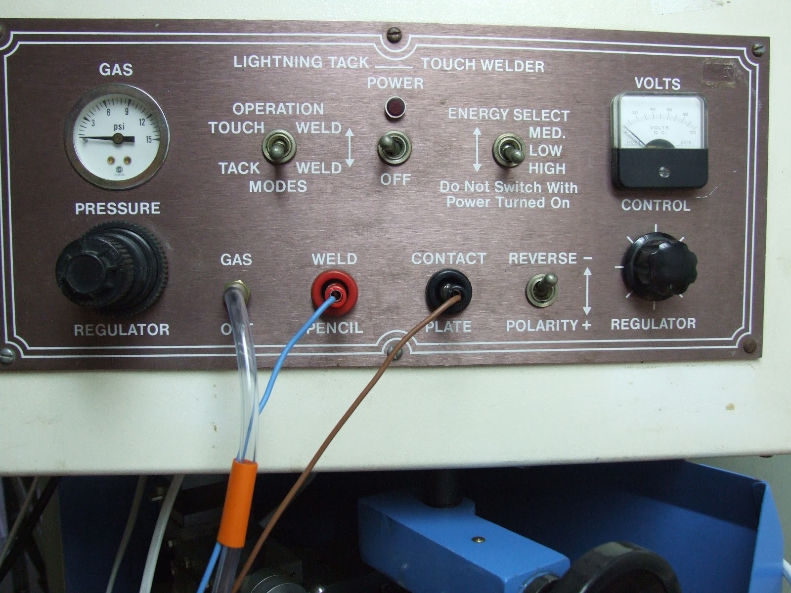
These
pictures of an ABI welder were sent to me by a good friend, thank you
Borowski!!!
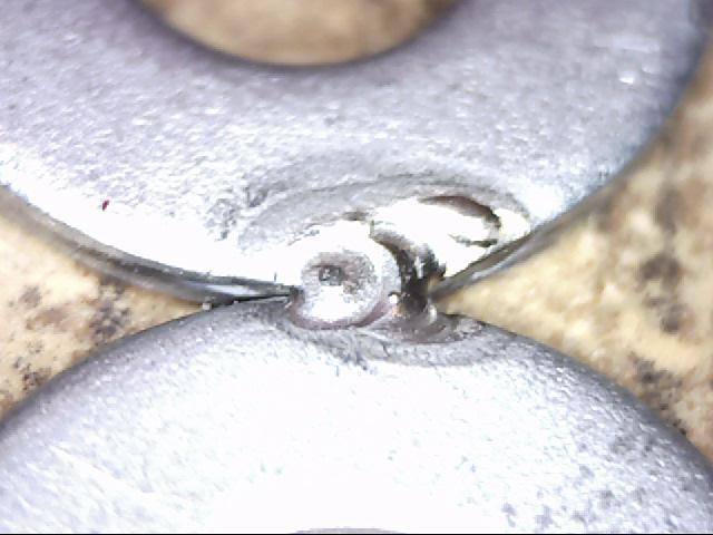
This
welder looks very primitive to me and basically uses a high voltage low current
pulse to start the plasma flame and then a capacitor is discharged a couple on
microseconds later to produce a very hot plasma flame. The problem with these types
of high voltage starters is that when welding inside a tube or a channel
where the sides or a spot on the work piece is closer than the spot that needs
to be welded, the high voltage arc will jump to the closest spot and miss
the actual point that needed to be welded.


WELDER PROGRESS 11/17/2012
The start circuit works very good but I'm not happy and are trying to get it to work better. What i see is that the capacitor discharges to around 13 to 14 volt and then the plasma flame goes out. I read up and found on a couple of sites where they say that the lowest plasma voltage is about 14.6V. So this is normal...please help me out if this is wrong.
After some head scratching i realized what the problem was. The start of the plasma arc is using up too much energy and basically discharges the capacitor too far before a plasma flame gets lit.
I am working on a secondary start circuit and will hopefully test it tomorrow 11/18/2012 and will post the results if everything works out as planned.
After a successful test I will be able to move on to design the rest of this welder.
There are still lots to do, designing the power supplies for this welder.....so far three....I'm not sure if I'm going to make it switching supplies?? and then i have to design an agitating circuit which will help to weld metals that are difficult to weld with frequency adjust and pulse width modulation. I will also have to think how I'm going to control all of this, touch screen? or lots of buttons?
My main objective here is to try and make it as easy as possible to build and keep the cost low.
MORE TO FOLLOW.....